Announcement

Collapse
No announcement yet.

The Gaganator Project

Collapse
X
 
  • Filter
  • Time
  • Show
Clear All
new posts

  • #16
    Beeman,

    What size Gator , ATV tires do you plan on using on your 8-wheel project? I have a set of six hardly used 26 , inch Gators , size 12 x 12 , that I,ll make you a good deal on .
    Last edited by mudbug3; 11-14-2007, 02:47 AM.

    Comment


    • #17
      Mudbug,

      The largest I can go is 25... otherwise I'd totally be in

      Cheers,

      Beeman

      Comment


      • #18
        Not much more, but I put the diff jig onto the CV axles to see how everything worked out... Looks like I'll need to shave some metal around the frame where the axles come up. I'll have to think about this one a little... don't want to weaken the structure.

        Last edited by Mike; 01-01-2008, 05:32 AM.

        Comment


        • #19
          [quote=beeman;5440]Not much more, but I put the diff jig onto the CV axles to see how everything worked out... Looks like I'll need to shave some metal around the frame where the axles come up. I'll have to think about this one a little... don't want to weaken the structure.
          [quote]

          Hey Beeman
          I've been silentyl watching this project. I can't be silent anymore, now it's starting to look like something.I like the ground clearence your gonna have. How much do you think? Will those CV's handle that angle? Looks pretty steep.What kind of plans do you have for a tub, if any? Keep up the good work, we're watching you.
          Whipper
          Last edited by Mike; 01-01-2008, 05:31 AM.

          Comment


          • #20
            I had a problem somthing like the clearance issue you are having. I would cut a notch out of the frame, use a peice of angle iron inverted into the frame tube, and use sheet steel to cap the ends of the angle. Using a peice of 1" angle would gain you 1/2" clearance. Just my 2cents!

            BTW: That's gonna be one killer machine!
            Jeff
            02 Argo Bigfoot

            I never get lost : I take expeditions!
            I'm guided by the Magic 8 Ball.

            Comment


            • #21


              Wipper,

              as for the CV axle angle, I have done some research and it looks like the max might be 45deg. To me this seems a little steep... and of course, it depends on the build. 25degs is another max I've heard (I've also heard of a 90deg CV joint )... so, basically, I'll take it as it comes.. if it's too steep, I'll lower it, if it works.. It'll keep it in place. The animated gif looks like a good 45.. but mine arn't built like that (I've got three rollers and the rollers are locked in place). Meh.. design - no matter how hard you try to make it real often comes to somesort of rig job to make it work (just a little less riggin :P).

              As for the clearance, I've got about 10" right now in the center- but that's on blocks.. so maybe minus an inch or two under load (and softer springs), plus 2" from 25" tires.... probably comes to exactly how it sits now... around 10"

              I have thought about tub design, and the basics are as the beginning drawings... but I plan to add more "anger" into the look, maybe with an air intake... and a nice grill. The lights I am thinking to try and incorporate a hot rod style (free standing)... but unsure... I'll probably throw up a couple new designs of the look in a couple weeks.

              Greasemonkey,

              Yeah... I think that's the only way to go. I might add a hoop of round tubing to the top to counter the cut... just to be on the safe side (probably small and bolted on so I can get the axles out in a change).

              Thanks for the input guys... I hope to have more progress in the near future.

              Comment


              • #22
                A possible tub design..

                Comment


                • #23
                  I like that, especially the Argo-like raised section of the "hood".

                  Comment


                  • #24
                    Well, I was in and out of the shop a couple times working on the diff frame and after a lot of frustration 
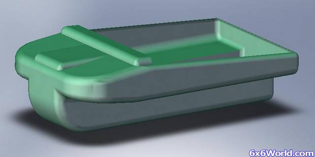
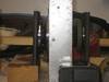
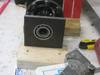
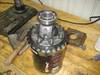
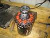
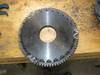
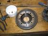
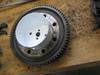
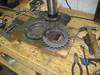
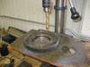
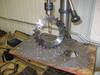
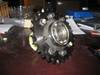
I decided to go a different route to hold the diffs. The problem is comming from trying to form my own sockets for the bearings out of 1/4" 3 1/2" tubing, cutting and bending down to the right diameter, as well as with the crappy used snow fence posts I'm using for the trusses (full of bends and what not).

                    New approach - find the right sized bi-metal hole saw and make a socket out of 5/8" flat steel, supported directly from the chassis and brace bars to each socket to counter the compression and twisting action.

                    I should have pics by the end of Sunday :P

                    Last weeks rendition:

                    untitled.jpg
                    Last edited by Beeman; 12-15-2007, 01:10 AM.

                    Comment


                    • #25
                      The new diff frame in concept form... I've already cut four of the eight steel plates for the middle(s) and bought some tubing to replace the old crappy snow fence metal..... it'll be nice to work on straight stuff again..

                      diffframeII.JPG

                      Comment


                      • #26
                        some pics of trying to align the sprocket on the diff...


                        Last edited by Mike; 01-01-2008, 05:30 AM. Reason: linked pictures to save bandwidth

                        Comment


                        • #27
                          gagonator.....

                          praise praise..haha

                          Comment


                          • #28
                            Beeman ,

                            Those pics you posted were exellent ! What kind of camera did you use to take them?
                            Last edited by mudbug3; 12-29-2007, 06:11 PM.

                            Comment


                            • #29
                              Originally posted by mudbug3 View Post
                              Beeman ,

                              Those pics you posted were exellent ! What kind of camera did you use to take them?
                              Canon powershot SD600. Ever since my first powershot 100, I have always bought canon digital cameras for their compact form and excellent quality.

                              As for the project, worked on two more bearing/race pieces tonight - one more left and then should be able to weld up the frame and show some good pics.

                              Comment


                              • #30
                                Well, the first attempt at metal working the sprocket worked - but I wasn't happy with how unclean it looked. It's hard to get a clean cut with a plasma torch (or I'm just crappy at it :P). So, while working on getting the water/plumbing & electrical working for my washer and dryer (for my house) I decided to use the old gear that the diff used to hold as a jig. Measuring the center hole (that I had cut with the plasma) I found out that it was almost perfectly 3 3/4" in diameter... which was a size that I could probably find a hole saw for. And sure enough, when I was looking for a hole saw to cut my dryer vent hole at 4" I also found one that was 3 3/4". And so, after finishing up the laundry job for the wife, I got to working on the sprocket again.....

                                Pic of the first attempt at the sprocket:


                                And a bunch of pics showing my second attempt:


                                And the final product:


                                And a google video of the final product:

                                MVI_0944.avi
                                Last edited by Mike; 01-01-2008, 05:27 AM. Reason: linked thumbnails for multiple pics

                                Comment

                                Working...
                                X