
Been bating this one around in my head for a while. How do we make a springer using as many OEM parts or low cost parts as possible? Use low cost lower A-arms from Speedway Motors, etc. Get junkyard uprights from a CIVIC or the like. Run an upper strut to the new roll cage for support. Use modified replacement CV axles like these where one side takes the place of current 6x6 axles in the tub (need to add bearings and mount chains) : http://www.rockauto.com/getimage/getimage.php?imagekey=2975874&imageurl=http%3A//www.rockauto.com/info/EMPI/80-2661.jpg
Tie the lower arms into the stock chassis at the bottom of the tub. Tie the struts into a plate that ties directly into the cage. Could have front and rear steering???? Each side could be drive by a conventional transmission with locking diff. Just some ideas.
-
Concepts
Just noticed this thread, worked on a few concepts of a suspended walking beam, trailing arm design for a custom 6x6, but never had time to pursue. A friend of mine (Marco in Switzerland) built an articulated swing arm 8x8 called the X-Cat. He used a salvaged Arctic Cat ATV for his drive system. He is a very talented craftsman. There are many YouTube videos of it in action.
Attached is a pdf of my concept dwgs and a video link to Marco's X-Cat.
Leave a comment:
-
Right. Going to use stainless on the outer shaft for that reason.Leave a comment:
-
Jerseybigfoot
No spline needed. That is the secret sauce. The knuckle (bearing housing) holds an LM76 BullDog bearing that is very low friction and accommodates the rotational and linear movement. The solid bearing slides up and down the shaft without a mechanical bearing. These bearings are made to work in slurry's where traditional bearings would fail.Leave a comment:
-
you are going to need to spline the axle to allow the U joint to operate a a different swing radius than your lower a arm. otherwise it similar to the old springer designs. some had the u joint at the center line of the A arm pivot. also hustlers have a large box on the drivers side to give the engine clutch clearance. this design lends itself better to an Argo ,Max , or Attex.Leave a comment:
-
springer setup
One image is for a plastic mount with a backer plate.Leave a comment:
-
I do have an idea on the torsion. I have not yet modeled the carriage yet but I think there may be a solution to putting a torsion bar in advance of the axles then using a double u-joint with my bearing hub revised. Would be wider than stock but less than current design.Leave a comment:
-
Right.
I have built a quick model to show the plastic mount with the current design. I would need about 10" of head space from the cl of the axle to the top of the bracket. I dont have that on my 950 so the question is does the 980 have the headroom?Leave a comment:
-
That's exactly what I was thinking. Oil bath chain box, with coilovers on the inside of the tub. You could even run tracks over that kind of setup, since all the movement is up and back instead of up and out.Originally posted by thebuggyman1 View Post
Shawngray,
You could also reduce some width simply by using a different wheel offset. A 5+2 offset would put the track a bit closer to the tub, but still not as close as a trailing arm system. Remember that the more you shorten the A-arm the less travel your suspension will have.Leave a comment:
-
Stonewall,
In looking at the design I believe I can tighten it even further by reducing the a-arm dim. I will try it as send an offset measurement. I went a little wider for stability.Leave a comment:
-
bottom tub.jpgStonewall,
Sorry for hijacking this thread. I may need moved.
I looked at the offset and it seems with my design the additional width is half a tire on each side. Less than that of a CV.Leave a comment:
-
Stonewall,
Correct. My design does add width but less than a CV setup. However a trailing arm using a similar bearing design could be done cheaply I think. I found some torsion stubs for #500 pounds per set which is a little stout. Moving to a shock or airbag setup might not be too difficult.Leave a comment:
-
A trailing arm/chain box system would work well, especially since the chain box could be an oil bath.
Trailing arms also give a better ride because they swing back slightly as you hit a bump, instead of just up.
[IMG]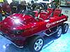 [/IMG]
[IMG] [/IMG]
Leave a comment:

Leave a comment: