Announcement

Collapse
No announcement yet.

hustler 5 pole key switch wiring diagram

Collapse
X
 
  • Filter
  • Time
  • Show
Clear All
new posts

  • hustler 5 pole key switch wiring diagram

    Ive a 5 pole key switch. I need the diagram of that baby and how the hustler is wired. Hustler has a BS 18hp & a 3 post solenoid.

    zoood

  • #2
    Check my Gallery.. Dan67, Hustler 980/950 Build. I have several diagrams for Briggs 5 pole and 6 pole. Check them to see what resembles the wiring on your motor. Its either..


    or..


    Or you can upgrade to a 6 pole switch, I have the diagrams for those as well in my Gallery..

    Comment


    • #3
      I see that my key switch didnt have a ground. Also instead of hooking up the amp gauge. How would I tie in a voltage gauge instead?


      Originally posted by Dan67 View Post
      Check my Gallery.. Dan67, Hustler 980/950 Build. I have several diagrams for Briggs 5 pole and 6 pole. Check them to see what resembles the wiring on your motor. Its either..


      or..


      Or you can upgrade to a 6 pole switch, I have the diagrams for those as well in my Gallery..

      Comment


      • #4
        heavy guage red wire from battery to ignition switch terminal "B"
        Black wire from frame to switch Terminal "G"
        yellow wire from switch pole "S" to small terminal on solenoid
        green wire from "M" (magneto) terminal on switch to the kill stud on the engine... flat twin briggs it should be under the intake manifold halfway between the carb and the cylinder closest to the front of the machine.
        "L" terminal on the ignition switch is where you hook the headlights... I also tie the charge wire here (single red wire coming out of the voltage regulator) so that power from the battery can't backfeed when the switch is off (this can fry a briggs regulator).
        If you want to run a volt guage, I would also tie it into the "L" terminal. that way it is turned off when the ignition is off. hook the positive to the "L" and the negative to "G"
        A well regulated Militia, being necessary to the security of a free State, the right of the people to keep and bear Arms, shall not be infringed.

        Comment


        • #5
          Looking at the diagram I see that the number 5 on the switch back is for the lights. Turned out that the toggle I was using for the lights, (cause Im trying to make the side dash panel look as nice as Dan's.) 
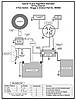
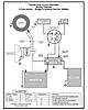
was faulty. However the rest of the wiring was hooked up correctly except for the key switch, it wasn't grounded.

          Also I love this sight! No BS! Get answers heck of a lot faster and correct too compared to most motorcycle sites I visit with questions.

          Thank you both!
          zoood

          zoood


          Originally posted by racerone3 View Post
          heavy guage red wire from battery to ignition switch terminal "B"
          Black wire from frame to switch Terminal "G"
          yellow wire from switch pole "S" to small terminal on solenoid
          green wire from "M" (magneto) terminal on switch to the kill stud on the engine... flat twin briggs it should be under the intake manifold halfway between the carb and the cylinder closest to the front of the machine.
          "L" terminal on the ignition switch is where you hook the headlights... I also tie the charge wire here (single red wire coming out of the voltage regulator) so that power from the battery can't backfeed when the switch is off (this can fry a briggs regulator).
          If you want to run a volt guage, I would also tie it into the "L" terminal. that way it is turned off when the ignition is off. hook the positive to the "L" and the negative to "G"
          Last edited by zoood; 02-04-2012, 07:57 PM. Reason: answered my own question

          Comment


          • #6
            I ran into problems. I attached a diagram of the wiring schematic I'm using and a few extra switches. The back of the key switch, I labeled with what color wires there were.
            Following previous directions. Only the engine cranks. The light switch I'm using works in reverse. Meaning when i hook up the battery. The lights lite without the light switch being enabled. When I enable the light switch. The LED indicator lamp lights, but the lights go out! On my key switch or the solenoid. There's no terminal labels. The two other switches I have in the diagram work fine. With the diagram I provided and the new light switch I want to use. Can someone please connect the dots for me? and label them as well?


            zoood

            Comment


            • #7
              Clean the back of the switch very well. There should be a letter stamped on the spade terminals or right beside each terminal to identify each. Sorry I don't still have the old switch, I threw it in the trash because I did not need it. I used the new 6pole switch that came with my 23hp vanguard.

              Comment


              • #8
                I went and bought a new key switch. The old one had no markings. I rewired the plug for the switch like racerone3 suggested. It didnt work correctly. I went through everything and found a connection that should have went to ground, but was hooked up to +. After correcting that. It all works fine. Now I can throw my comb away! Again thanks for your help.

                RJ


                Originally posted by Dan67 View Post
                Clean the back of the switch very well. There should be a letter stamped on the spade terminals or right beside each terminal to identify each. Sorry I don't still have the old switch, I threw it in the trash because I did not need it. I used the new 6pole switch that came with my 23hp vanguard.

                Comment


                • #9
                  np, glad everything is working now!

                  Comment

                  Working...
                  X