
 Tweet
Tweet
So i'm repowering my old 70's argo with a new 18hp briggs vanguard engine. The machine had a 16hp tejunksy in it originally. My concern is with drilling the new mounting holes in the plate. The hole pattern is the same but i need to move the engine back roughly 1 1/2 inches to make room for the oil filter. I purchased a longer belt to make this possible. What i'm worried about is if i just move the holes straight back will i get proper alignment between the main clutch and secondary clutch? It looks pretty close lining it up by eye, maybe a little bit off to the right (looking at it from the front of the machine) Though i'm thinking that's probably how it should be as the clutch will draw the belt closer to the motor as it closes. am i correct? i want to be sure i get it right on the first shot. heres some pics of what i'm looking at to try and give you a visual of what i'm talking about:


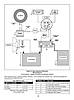
My next question is about the electrical hookups. I tore all the old wiring out and i am starting from scratch with new wiring, but honestly i dont have a clue what i need to hook up to properly wire in the motor and make sure it's charging the battery correctly. does anyone have any knowledge of this who could give me a diagram of the wiring or a link to website which has a wiring diagram perhaps? Heres a pic of what i have on the motor, i just need to know how to properly connect it to the battery.

Any help you can give would be greatly appreciated. I'm really excited to get this machine up and running. the snow's piling up and i can't drive it yet!
My next question is about the electrical hookups. I tore all the old wiring out and i am starting from scratch with new wiring, but honestly i dont have a clue what i need to hook up to properly wire in the motor and make sure it's charging the battery correctly. does anyone have any knowledge of this who could give me a diagram of the wiring or a link to website which has a wiring diagram perhaps? Heres a pic of what i have on the motor, i just need to know how to properly connect it to the battery.
Any help you can give would be greatly appreciated. I'm really excited to get this machine up and running. the snow's piling up and i can't drive it yet!

 Would it be as simple as setting the old motor with the clutch still on it, on a flat surface(bench). using a square setting on the bench, place it up against a spot on the clutch that is easy to see, then measure from the square to the center of the mount holes. Now take the clutch and put it on the new motor and repeat the process. This should tell you if you have to offset the new engine or not. Keep in mind that I am a carpenter and most every problem I tackle to get measurements of this nature I will use this process. Works for me. Hope it helps.

Comment