Announcement

Collapse
No announcement yet.

Conquest Big block Kawasaki Upgrade

Collapse
X
 
  • Filter
  • Time
  • Show
Clear All
new posts

  • Conquest Big block Kawasaki Upgrade

    Been done at least twice. Youtuber guitarhack42 posted a chronicle of his swap and Rock Doctor provided links in this thread. Rock Doctor also made this swap and proves it in this thread.

    So, high elevation playing in the snow on tracks had convinced me that I NEEDED more horsepower. In this thread I mention a pretty easy engine modification that gains a smidge more than 10% horsepower for the FD620D and I was pretty sure this is the route I was going to pursue. Later in that same thread I explain how I ended up with a big block Kawasaki FD791D sitting on my garage floor.

    Dimensionally, what are we talking about?

    FD620D Dimensions.jpgFD750D Dimensions.jpgDimension differences.jpg

    (left is Fd620D right is FD750D)

    Hmmm, the PDFs were too large to upload and the jpg conversion leaves a bit to be desired but these are the documented sales dimensions from Kawasaki. A search should find them - I downloaded them when I found them so I'm not sure where they came from. The spreadsheet shows some important dimensional differences. Units are millimeters.

    What we see is that there are mounting bolt locations on the 750 that will put the flat face that the driven pulley indexes on in plane with the same on the 620 and 8.5 mm higher vertically. Close enough that this is no issue. The gross dimensions (think of it as a box) tell us that the full engine package of the 750 is slightly smaller all around except for and aft by a few millimeters. The shaft is 16mm too long and the radius from the shaft to the shoulder is 2.5mm greater.

    From this I will use the same bolt holes for mounting but will need to drill them a bit larger. I mounted the engine in my turret lathe:DSC00629.jpg to cut off the extra 16mm (used a hacksaw and beveled with a file) and drill/tap the center hole. You can choose to cut the bolt shorter. As for the radius change I will mill the driven pulley, probably in the same turret lathe , to put a 2.5mm larger bevel on the inside surface.

    There are other dimensional issues to deal with that will make more sense to talk about as I get to them. In fact, right now I have the power pack apart and I'm about to modify the engine mount. I'll take pics.

    There are fuel system differences. I have stuff to show for that.

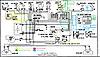
    There are electrical differences. I have drawings to show this.

    I go slow because I do lots of stuff. The project stalled last spring because of walleye tournament season and garage remodel and ...

    ... but now I'm on this again.

    Oh, and since the power pack is out I am throwing installing a bilge pump and upgrading the front axles to HD because it should be pretty easy now. Also, the 620 has an alternator and I am going to move that to the 750 - there are quite a few dimensional issues with this.

  • #2
    Power Pack frame mods

    DSC00764.jpg

    Volumetrically the new engine fits pretty well in the space of the old engine. Fd620d is on the left. This doesn't mean we don't have clearance issues to deal with. The footprint of the FD750D line of engines is just a little larger all around and although the mounting bolts are in the same place, they are larger bolts.

    DSC00763.jpgDSC00778.jpgDSC00779.jpg

    Pic 1 is original. Pic 2 shows what needs to be removed. The vertical needs to be moved back 20mm but I think I moved it a tiny bit more to allow for any inconsistencies in my machine shop. I drilled the bolt holes larger with a Y drill. The cutting I did with a cutoff wheel. Pic 3 is the finished mod done with a Lincoln V205-T and a bit of flap disc sanding.

    DSC00781.jpg

    Next clearance issue for this frame is the brake cooling air duct. The engine mod to the frame in effect pushed into the space this occupied. There is a little room to take advantage on the front where the rotors fit into the ductwork so I split the difference a bit. In the picture above you can see that I extended the cutout and slots 17mm to move the whole of the duct back. The starter on the engine interferes with the duct so I took a small heatgun and pressed a notch in the duct for clearance. I used a cutoff wheel and dremel for the metal cutting and a bolt to press the notch into the plastic. If you want it to look better you could use a large piece of pipe. I just reached over and grabbed the transmission mounting bolt. It was close.

    Next up will be drive pully mod and alternator bracket fabrication.

    Comment


    • #3
      If anyone else wants to see how this is done, I would recommend paying attention to this thread. John has proven to be very meticulous in the past, so this should spell everything out rather well.
      Personally, I just went by Guess, by Golly, and made it work.
      Looking forward to seeing how I should have done it, lol.

      RD

      Comment


      • #4
        JohnF, there is a brake duct relocation kit available, moves the duct to top of trans between clutch shield and m/c mounts. Will be helpful if you need to get at starter.
        sigpic

        My new beer holder spilled some on the trails - in it's hair and down it's throat.
        Joe Camel never does that.

        Advice is free, it's the application that costs.

        Comment


        • #5
          Hey guys.

          Put the power pack back together this evening. The 17mm adjustment for the brake cooling duct is more than you need. Maybe 10mm too much so if you extend about 10mm you'll be alright.

          DSC00783.jpg

          You get most of the needed clearance via the notch.

          ARGOJIM, I did not know that - sure enough -Argo part 668-04 - look for the online installation PDF as well. I'm not going this route nowwww But it does simplify the process.
          Last edited by JohnF; 12-03-2013, 10:25 AM. Reason: Added photo

          Comment


          • #6
            clutch mod and tuning thoughts

            As I mentioned the clutch needs to be modified to fit a larger shoulder radius.

            <hmm, the "attach inline" isn't working and I'm too lazy to track it down - pics are here>

            Before - after. [EDIT - Doing a preview I see that it is really After - Before.] The clutch comes with a bevel to clear the FD620D 1mm radius at the shoulder. I used a small die grinder stone and a bit of sandpaper to re-profile to a round-over. I eye-balled until I thought I was close, smeared a very thin layer of anti-seize on the work piece and slid it onto the shaft, worked down the high points, repeat. It took me about an hour but that includes taking the clutch apart an putting it back together - I didn't want to get grit inside of it.

            CVT tuning: From the PDF you can see Argo's suggestions for weights for different elevations. It looks like they are using a typical 3% loss per 1000ft change so the 20HP is about 14HP at 10Kft. The FD750D (using Kawasaki's old methods) is a 27HP engine and the FD791D is 29HP. This means at 10kft we are talking about 19HP and 20HP. The largest weights I have are 260g - perfect for higher elevations. I can't find larger weights so I am hoping these will work okay but I will be watching for belt burning at the drive pulley. That is, there really isn't too much I can do except fabricate my own weights or bump to a newer model CVT.
            Attached Files

            Comment


            • #7
              Electrical

              I'll start with the diagrams of what we have and what we wish to accommodate.

              Conquest wiring.jpgFD620D wiring.jpgFD750D wiring.jpgFD791D wiring.jpg

              All of the engines use the same 6 lead packard connector but the leads are not the same so don't go thinking you'll just plug into the new engine all will be well.

              On the larger block engines the voltage regulator is part of the engine (attached to the radiator bracket) and the wiring for it is included in the harness so we can remove all of the wiring for it.

              The FD620D family has electronic ignition and the FD750D family has solid state ignition which sound sort of electro-geeky similar but they aren't. Electronic ignition uses circuitry similar to a computer and must be powered to make ignition happen; it requires a battery. Solid state ignition is the modern magneto ignition whereby a magnet on the flywheel passing a coil creates the electrical energy for ignition. You "shut off" electronic ignition by powering down the ignition module (they have a few names, on the FD620d it is called the ignitier) and for solid state ignition you give the ignition energy an easier path to follow than through plugs by "grounding" the ignition circuit to the engine block.

              Okay, the point of all of the ignition talk is to point out that the key switch on a conquest ('97 anyway - more later) is set up for electronic ignition and has no support for any other style ignition. Both ignition systems are common for small engines and it happens that the response engine (B&S) uses solid state (or magneto anyway) so I set out to find me a key switch from a response for the conversion. In doing so I found that the current key switch part that Argo sells covers both ignition types. I don't know when Argo made the change but I wouldn't be surprised to see later conquests that have key switches with the G and M terminals.

              Alright - the plan:

              Argo repower wiring.jpg

              This is the page I had sitting on the bench while I made the changes. There is one difference though, "female bullet to white wire on engine" also has a relay. I don't know why I forgot that in the picture. Yes, I used the relays; their purpose is to protect the ECU from errant voltages. Make sure the relays you buy are at least 10Amp continuous duty and have suppressed coils. I got mine from ebay with mounting brackets. I forgot to capture that data but for the rest:

              1 Key switch: Argo part 127-105 from an argo dealer
              1 Mouser part 829-02973778-B (packard 2973778) (A terminal of key switch)
              1 Mouser part 829-02973422-B (packard 2973422) (rest of key switch)
              1 Mouser part 829-08905177-B (packard 8905177) FD791D ECU connector
              6 Mouser part 829-12124522 female terminals for the packard connectors (on key switch)
              3 Mouser part 829-02965481 male terminal for packard connectors (ECU connector)
              1 Argo 634-08 lamp (the big red lamp used on conquest) ECU diagnostic lamp.

              Along with bullet terminals, marine splices and anderson connectors that I just have around.

              Hmm. Continue - I reached my attachment limit...

              Comment


              • #8
                I noticed that when I attach pictures they seem to be automatically shrunk. This is alright for most of them but the detail on the one I called the plan can be important so I uploaded the larger picture to the gallery here:


                Alright, back to it:

                DSC00805.jpg

                Upper left clockwise: relays, ECU connector, anderson connector, bullet terminals, splice, key switch, lamp. Also you can see the packard terminals are in bags.

                I followed the plan, unwrapped the harness in the Conquest and ended up with:
                DSC00809.jpg

                . Lower right (red) Battery to starter (and then to rest of vehicle)
                . Green wire - this is the start circuit from the key - I will trim and fit once engine is installed.
                . White 6 lead connector - this is the engine connector.
                . Big fat black with silver tip - this is the engine ground cable.
                . Brown connector and white with blue tip - these will only be on the FD791D installations - ECU connections.
                . Red (and there is a black behind it) anderson connector - I used this for my alternator sense and lamp leads.
                . Thin black and white wires - these are leads for the tachometer I've added. They too will be trimmed and fitted once engine is installed.

                DSC00810.jpg

                That's the under the hood look. The red wire hanging free is a lead to 12v accessory plugs that I hadn't yet finished installing.

                I don't have a picture of the dash side but here is what I did: I have the key switch hole and the choke lever hole open and my plan was to simply put the ECU lamp in the choke lever hole. Well, the new key switch diameter is a bit smaller than the old one and with the packard connector attached at the back it is a super tight fit behind the dash as there is little clearance between the dash and the fuse block so I plastic welded both holes a little smaller and installed the key switch in the choke position and the lamp in the old key position. In the future I would solder pigtails to the back of the key switch instead of the packard connector and then I think it would fit fine.

                Comment


                • #9
                  John, I (& I assume a couple others) are following this post closely. Thanks for being so exact with explanations, pictures, diagrams & reasoning. Going for more horsepower has always been in the back of my mind & maybe the near future.
                  I have no other input but wanted you to know there are a couple of us watching closely & paying attention.
                  Thanks for posting.

                  Comment


                  • #10
                    Fuel delivery

                    Moos-a-boo (and others) - my pleasure. Sorry the story is so slow to unravel but I am an incurable many-irons type of person.

                    FD620 Fuel Req.jpgFD750D Fuel Req.jpgFD791D Fuel Req.jpgFD791D Fuel Req 2.jpg

                    Those are pages from the service manuals. The first is what we have followed by FD750D requirements and 2 pages for the FD791D.

                    Good news is that if you are doing an FD750D upgrade then you are done here.

                    For FD791D folks the important information is: 120ml/3 sec at about 27PSI. I could buy a kawasaki fuel pump but boy-oh-boy are they expensive. I searched down some aftermarket car fuel pumps. To do that I had to convert 120ml/3 sec into about 38 GPH. (As for me, most fuel pump charts are in GPH) I want my pump to self prime sitting just above the tank - this is really important in the decision.

                    I came up with a few that should work:
                    Walbro GSL393 (40GPH @ 30ish PSI)
                    Airtex E8228 (38GPH @ 30ish PSI)
                    Walbro GSL391 (50GPH @ 30ish PSI)

                    MTBF of the GSL393 is supposed to be really good, they are used a lot by auto hobbyists, and the lawnmower mechanic that sold me the FD791 top sort of suggested that he has had good luck with it - although he would sell me a Kawasaki pump.

                    I picked up a GSL393 from ebay including install kit for about $100 US.

                    <Next - more pictures>

                    Comment


                    • #11
                      Fuel delivery 2

                      DSC00819.jpgDSC00818.jpg

                      Okay, the first pic is to show the parts I used.

                      The hose at the top is 15 feet of Gates Barricade 5/16 fuel injection hose. This can be expensive but I watched ebay and a NAPA store ran some through on a deal. The number on the side of the box is H357. I don't show it but I also bought some good rubber 1/4 inch fuel hose for the fuel return line. 12 feet.

                      Clockwise is a [15-04935 7005 FUEL TANK ACCESS ELBOW] that I got from a place called California Power Systems but the package came from Aircraft Spruce. Next to it is a bit of clear fuel line I intended to use on the end of the elbow down in the tank but I didn't. It has a 1/4 hose barb on one end. You drill a 1/2 inch hole, pop the grommet inthe hole and then push the elbow into that. This is for the fuel return line.

                      Then the fuel pump all dressed up for install. On the suction end I installed a fram G22 filter.

                      Next (still clockwise) is the fuel pickup tube from the tank and the fuel pickup I replaced it with. This is Argo part 608-84 which gives me a 5/16 barb, no pickup screen, and a pickup tube that is too long. I held the original to the new and cut it off. This gave me a bit of the black tube that I used on the fuel return.

                      And last is injector hose clamps. I got 10 off ebay.

                      Hmm, I forgot to put the bosch high pressure filters in the picture but I also got some high pressure fine filters (set of 4 Bosch 0450905002) that I will install as near to the engine as I can.

                      That last picture is everything installed. You can see where I installed the fuel return; it's not in the way of anything, that spot is flat, and you can get to it with a drill.

                      I used 10-24 screws to hold the pump to the tube.

                      Comment


                      • #12
                        It seems like a lot of work to upgrade for a few HP. Especially, when you can still buy the original engine and drop it in.

                        Comment


                        • #13
                          Originally posted by shot410ga View Post
                          It seems like a lot of work to upgrade for a few HP. Especially, when you can still buy the original engine and drop it in.
                          An easy and inexpensive 15% increase in HP can be done by converting your FD620D to an FD661D. There is a thread in the engine forum about this.

                          This is a 35%-45% increase in HP. Roughly sea level performance at 10K ft. It should be much easier for me to crawl around on the trails near me.

                          FD620D sea level 20HP @10k 14HP
                          FD661D sea level 23HP @10K 16HP
                          FD750D sea level 27HP @10K 19HP
                          FD791D sea level 29HP @10K 20HP

                          REF: An online BHP calculator

                          I do know that when I take the machine to the ranch in Nebraska (2Kft elevation 19HP) it is a much different machine. Easily climbing, turning, etc. so I know 19HP would be awesome.
                          Where I live (6Kft 16HP) I don't experience problems putting it on the trailer and moving it around the house but I can't really work it out so I don't have a feel for the 16HP point.
                          But at 8K or more (14HP and yes, with smaller CVT weights) it gets to be a drag. I can move and jerk around turns but I spend a lot of time in low gear. (I do have the G transmission)

                          But you are right, it is not for everyone.

                          Comment


                          • #14
                            Hey, I am enjoying this post but I already have the FD750D motor in my MaxIV. My question is: are there any performance parts made for the FD750D. I would like another 15 horse power or so. Does anyone know how to modify the governor so I can get this engine to rev to 5000 rpm?

                            Comment


                            • #15
                              Alternator Install - Inside bracket

                              I hinted that I planned on installing the alternator in the wiring post so here it is.

                              The brackets for installing the alternator on the FD620D won't work on the FD750D engines for a couple of reasons:

                              1. It would cover the one accessible oil drain.
                              2. The length of the crank is longer and it shows in the flywheel position.

                              Since the flywheel is pushed out on the FD750D engine, it is a lot busier in the area under the radiator and around the flywheel.

                              DSC00760.jpg

                              First up is the pulley and that is a picture of the FD750D with the fan belt sheeve from the FD620D that has the pulley standoffs integrated. It appears to be a standard thing for the FD620D engines. This won't work because it holds the pulley too far out and we wouldn't have clearance to install it into the Argo.

                              The pulley is the alternator pulley from the conquest alternator kit. I will be reusing everything but the brackets from that kit.

                              You will need about 2ft of 1/2 x .083 steel tube. I bought 03-02710-2 4130 STEEL TUBE 1/2X.083 2FT for $8.00 US from Aircraft Spruce & Specialty CO.

                              I made three spacers that were .45 inches long and bought 3 shorter bolts (shorter than the 3 bolts from the FD620D) and installed the pulley onto the the flywheel. I apologize that I can't remember the bolt lengths but they are M8x1.25 bolts. I did go to the effort of attaching a dial caliper as I installed this to get it as concentric as I could. I do believe that it is worthwhile to get this as centered as possible.

                              Okay, next up is figuring out how to bolt an alternator to the engine. This engine doesn't leave a lot of options as it seemed that nearly everywhere I went I was in the way of something.

                              DSC00785.jpg

                              This picture shows the FD620D lower bracket bolted to the FD750D. I took a lot of pictures so that I could ponder while sitting in the warm house. You can see that I took the radiator off in this picture and that was done for contemplating and the killing of cardboard. Yes, a bunch of cardboard died in the making of this post.

                              The important part of the picture isn't obvious but notice the unused boss just above that bracket and the two bolts holding on the plastic flywheel cover at the bottom. There are steel bushings inside the plastic [important!].

                              Hmm, If I use those <sound of snipping cardboard> :

                              DSC00820.jpg

                              When I envisioned this part I was thinking 1/4 inch material and using nuts where the empty threaded holes are. That's 1/2 inch because that's what I had. I think it was a neighbors welding table as the surface was ground on and there were welding bits. If it looks like I cut it out with a torch that is because I cut it out with a torch. I did spend some time on the curve that is the lower right part of that bracket so that it matched the higher bracket exactly so that you can match drill those threaded holes.

                              Using that tube I mentioned above you need 2 spacers that are 1.5 inches and one that is 1.85 inches. The lower bolts are M8x1.25x75 and the upper one is m8x1.25x80. I would have used nord lock washers here but could find them when I wanted them so there are also split lock washers in there.

                              Want to make one?

                              [well shoot, I have scaled template in PDF but can't attach it here. I'll converse with Mike for a solution and then edit when I know]

                              Using the template: I covered the holes that are used to attach the outer bracket because you are supposed to match drill the brackets together. print and check that the scale is right - cut it out - attach to your metal - and cut/drill what you see.

                              Comment

                              Working...
                              X