Announcement

Collapse
No announcement yet.

Project: Argoceptor

Collapse
X
 
  • Filter
  • Time
  • Show
Clear All
new posts

  • #46
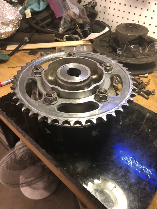
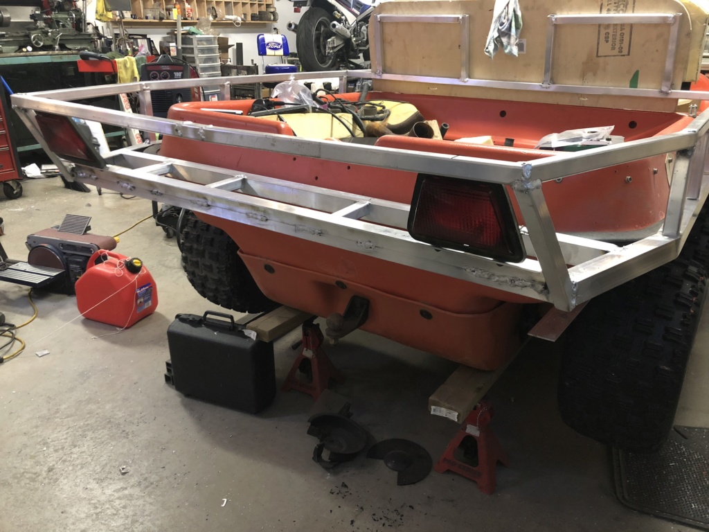
    Progress, but very slow progress:


    This is one of those things that just doesn't happen fast.

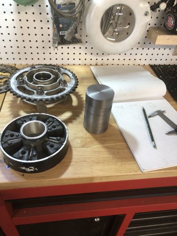
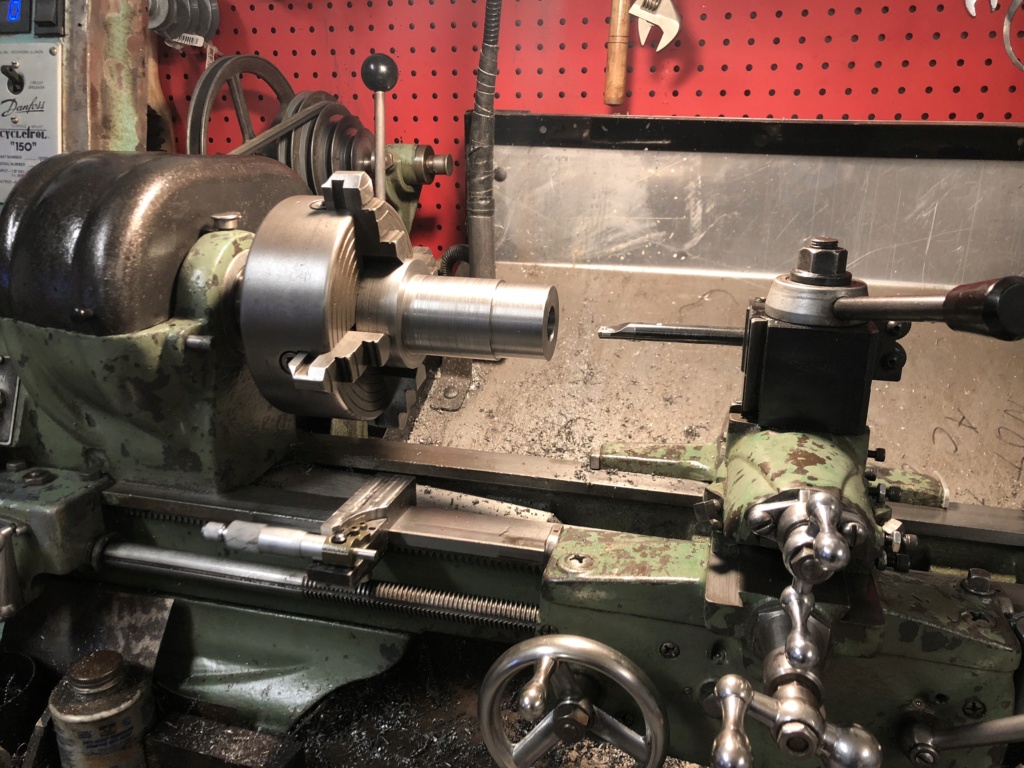
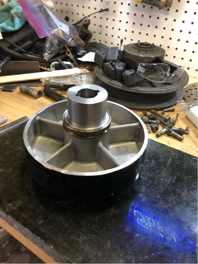
    I’m basically designing a “one off” drive system as I go, so its going to take lots of time and lots of thought before even making my first turn on the lathe.

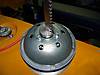
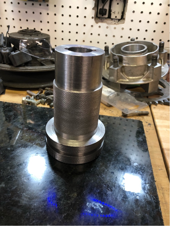
    All I’ve done so far is get my steel dimensionally true and cleaned/trued up the center hub drive bores.

    “Measure twice, cut once”....
    Last edited by great white; 12-16-2018, 09:58 AM.

    Comment


    • #47
      Well, it looks like this blunt, “un-boat like” lump is destined to be a 4-5 mph water borne vessel.

      I ran the calculations and it’s pretty much not practical to get this thing foil borne.

      The problem is the “take off” speed. In order to get enough lift to the wings at the speeds the argo is capable of, even with an outboard, the wings have to be prohibitively large. As in: stupid large.

      Its that damned argo hull again. If I could get 10-15 mph out of the hull, then the foils can be reasonably sized. But with the speed so low, the only way to do it is make the wing surface bigger and given the high weight and low speed, thats where you get in to the prohibitively large wing.

      On e out of the water; not a problem. It’s getting it out of the water that is a problem.

      Alas, I may have to settle for just a couple knots out of it as a top speed.

      Comment


      • #48
        Getting there. Slowly but surely;


        Still to do; finish the bore to final size for the transmission input shaft, machine a groove on the large diameter (so I have a place to grab with a puller when I need to remove it), machine a recess in the large diameter for the transmission input shaft retaining bolt and broach a keyway in the trans input shaft bore.

        Then its just shrink fit the CBR600RR wheel hub to the center diameter and it’s good to go. Couple more days of just lazy paced work should have it done.

        Then its make the offset sprocket for the engine, cut the chain to fit and move on to building the exhaust.

        Little work to wire it all up and then it’s ready for a test run. Maybe in a week or two’s time.

        Comment


        • #49
          I think I'm going to make change to the drive adapter construction. The mechanic in me really is rubbed the wrong way with shrink fitting the hub to the adapter and there being no way to remove it without, essentially, destroying it. After all the time put in to building it, I sure would be "peeved" if something broke and there were no reasonable way to salvage the remaining good pieces.


          So I think I'm going to change from a shrink fit to a press fit. This will mean less "holding power", but I'm going to fix that with another change. I'm going to machine a 3/8" plate to fit on the large diameter of the adapter and then grub screws through the aluminum hub to the 3/8" plate. The press fit will keep it running true and hold torque inputs, the grub screws will aid in keeping the hub from rotating and help handle the torque. Where the screws will be going is the ticker part of the piece, approx 0.250". It also open the option to use 5 to ten screws if I want (there's 5 compartments in the cush drive). One row in close to the hub, one row further out by the edges. It would pretty much have to blow apart for that to fail under load...


          I also decided to machine a groove in the large diameter. This will give me a place to attach a puller if/when I need to get the entire assemble off the transmission input shaft at sometime in the future. An example of needing to get it off in the future might be changing the driven sprocket to change the final drive ratio:


          The adapter is a slip fit on the shaft, but a little corrosion and we all know how easy it is for these type of things to "rust weld" themselves together over time. The ability to use the puller makes it feasible to actually get it back apart in that case! LOL!
          Last edited by great white; 12-23-2018, 02:50 PM.

          Comment


          • #50
            Actually, come to think of it, it might make more sense to just use a socket cap head screw and instead of going from the inside out, come from the back of the steel plate into the aluminum body.


            That would give me a full head to grab when installing and removing the components. For that matter, I guess I could use a standard head bolt if I wanted since I would no longer have to worry about the bolt interfering with the internal cush drive dampers....

            Comment


            • #51
              Test fit complete! Hub goes on the adapter slick as snot!


              I took a few thou off the adapter since last posting.


              I used the same technique I use to drop #2 engine bearings on compressors (one of the things I do/did at work is build jet engines from the compressor disc up).


              I placed the adapter on a nice thick, flat slab of granite (I have a couple pieces that I use for surface plates when building racks of carbs and such) for a couple hours to get it temp stable with the room. Then I wrapped the hub in tin foil and in to the oven it goes (500c) for 20 mins.


              I pulled it out of the oven, move quickly out to the garage, unwrap the hub and slide it down on the adapter. Goes right down to the shoulder with no problems. Well, a little drag, but that's more about me keeping it square than it not fitting.


              Since I need to still cut the keyway, I pulled it back up off the adapter before it had a chance to contract.


              I didn't want the hub locked to the adapter in case I mess up the keyway. I had planned to put it together and then cut the keyway, but common sense won out and said to fit the hub after cutting the keyway. It would suck to mess up the keyway and have to throw out the adapter but I'd have a major meltdown if the hub was locked on to the adapter and I flubbed the Keyway. If I broke the hub trying to get it off, I'd need another CBR600RR wheel to turn the hub out of! No thank you, I'll wait to make sure the keyway is right first!


              I worked it down to a measured 0.003" interference fit with maybe a +/- 0.001" error because of the measuring tools I have to use here. The way the hub slid on and off, it could very possibly be more like 0.002" or 0.001". Definitely won't go on when cold, so it's an interference fit for sure. If it is closer to 0.001, the back up plate and bolts I plan to add later will help lock it together to help deal with the drive torque it will see.


              So, tomorrow; build myself the broach and if time, cut the keyway. After that is done, drop the hub on the adapter and on to making the offset sprocket for the engine output shaft.


              Coming along nicely. Can't wait to take it for a proper rip across the field!


              Comment


              • #52
                After a totally frustrating and wasted day, I chucked the steel I had for the broach out the door.

                Seems the block I was going to use had a broken off drill bit in it. After trying to punch, drill and other wise remove it from the face of this earth, I gave up and fired it in the trash pile. Being xmas eve, it was that piece of steel or nothing. I figured that was it until Well after xmas day as most places around here where I can get a block of steel 1” or bigger are pretty much closed up until january.

                Got up this morning and in one last attempt a saving the project, I found an old 1 1/4 receiver hitch tongue in the back of the garage. I chopped it up and it machines like a dream. Some kind of mild steel, carbide tools glide right through it and leave a nice finish.

                So after half a day of dinking in the garage, I have the cross slide 5/8” holder and the 5/8” cold rolled bar built.

                Now to move on to making the rest of the broach/shaper attachment...,after the turkey dinner settles and I can move again that is!

                Comment


                • #53
                  Certainly not finished, but here's the "mostly completed" keyway cutter I'm building:


                  It's got a 4.5" stroke at the cutter position and has a .003" runout at the full length of the stroke. Pretty good for my first attempt at making a "shaper". I'm thinking of adding a gib screw a the front and back to take up even more of that .003". But it's certainly usable for my purposes as it sits.

                  Next is to mount the cutting tool at the end, make some spacers to replace the washer stacks you can see in teh linkages and some misc finishing up work. Eventually, I'll turn a handle for the end of the lever bar.Just to clean it up if nothing else.

                  Comment


                  • #54
                    Well, it's cutting:


                    But maaaaannnn.....is it ever slooooowwwwwwww. And it hooks and hangs a lot as well. The "dents" you see on the end of the turning are there because every time it would grab it would rack the turning, so I'd reseat it with a little bumping from the hammer. I eventually dismounted it, turned the jaws of the 4 jaw around and used the curved sections to hold the turning. That seemed to solve the racking problem. Probably should make myself a brass hammer too.....

                    I had to go though a couple grinding sessions until I got the cutting tooth just right. Very fussy to get the geometry just right so it would it cut the 1018 well.

                    I had to rework the "nose" of the bar a couple times to get as must depth as I could out of the blind hole. I also had to drill a hole in from the side to give the chips a place to break off. That was a fun task. One drill bit broke off and I had to abandon it in the hole, a second hole I messed up my measurement and it was too far up the bore, the third was in just the right spot. I'm not too worried about the couple extra holes, they're under the press fit hub once it's all assembled and the turning is so thick, a couple 3/16 holes are to going to hurt anything except my OCD.

                    I had several problems with the tool turning in it's mount, which caused most of the grabbing problems. I finally figured out it was actually the tool post turning in the compound rest. With the amount of force on the tool post, there was just no way to keep it from "creeping" as i worked the slotter. So I mounted up the Atlas milling attachment and that solved the problem. Side bonus is it also allows me to set the height precisely.

                    But I think it's going to take me 6 weeks to cut the keyway! LOL! Probably would go much better if I was cutting aluminum instead of 1018.....

                    Comment


                    • #55
                      "But I think it's going to take me 6 weeks to cut the keyway! "

                      Perhaps you can devise a bushing like the one here to back up the bar.


                      Not sure about how to shim a round bar though?
                      sigpic

                      Comment


                      • #56
                        Well, the fist keyway went all “wonky” on me at some point and I had to abandon it. Seems the cutting tooth shifted (or I misaligned it at some point) and it cut a ahoulder too wide.

                        So I flipped 180 out and cut a second keyway. That one went fine. Right now, I’m finishing up with a little file work to get the fit juuuust right and then it’s back to mounting the drive hub on the adapter.

                        Once thats done, i have to cut a simple spacer to postion it all correctly and then it’s on to making the offset sprocket for the VF output shaft.

                        But if a fight, but I’m getting there.....

                        Comment


                        • #57
                          Been a bit of work, but the input adapter is ready for the hub:


                          I knurled the hub shoulder in order to give it a little more "bite".

                          Then the hub goes into the oven to soak at 500f for 20 mins:


                          I wrap all my heated parts in tin foil for the heat soak. Occupational habit. When I'm building jet engines and fitting something like a #2 engine bearing, we always wrap it in foil to try and keep it as hot as possible on the trip from the oven to the compressor stand.

                          First, one last check of the input adapter to make sure it's microscopic clean (IE: nothing to hang or cock the hub when it goes on) and then the race from the oven to drop the hub down on the adapter:


                          Nice. Slams right home on the shoulder of the adapter. you can't even get a .001 feeler gauge under it:


                          I'd normally do what we call "drop measurements" to make sure it's fully home, but it's more than good enough as it is for this application. No light under the adapter works for me!

                          Now to wait an hour or so to let it all cool. The steel hub sucked up the heat right away and it's all too hot to touch now. Last hurdle is for the aluminum casting to NOT crack once cooled, meaning my interference fit is good to go.

                          Then it's make a simple spacer for the input shaft (to keep the sprocket properly positioned on the hub and help locate the adapter on the shaft) and it's done.

                          Then on to making the offset sprocket adapter for the VF750 transmission output shaft. Compared to the rest of the machining to this point, that's easy peasy!

                          After that, i can get on building the exhaust. That's will be "a treat", but no where near as exacting as all the machining work so far, so it will go together relatively fast.

                          Comment


                          • #58
                            Cooled off and assembled:


                            On the transmission input shaft:


                            Gotta say, I'm pretty pleased with my work!


                            I don't even want to think about how much it would have cost me to have a machinist build this chunk........ :o
                            Last edited by great white; 01-03-2019, 05:17 PM.

                            Comment


                            • #59
                              very impressive ! i understand your abilities now knowing you build jet engines . the final product should be quite the machine . johnboy va.

                              Comment


                              • #60
                                Took a break from the drivetrain and started some of the aluminum work:


                                You can see the front seat back frames. Right now, the seat back is straight across. But once done, there will be two seperate seat backs and a “step through” space in the middle. That will make it easy to drive into the water and move to the back to use the outboard. I may make it a “fold down” center or maybe a solid step plate like the Argo Huntmaster uses. Dunno yet, still thinking about that one...

                                The tail lights are from the 750 Interceptor. I had an extra in my spares pile so I could do L+R lights and keep with the “Argoceptor” theme. I needed to install rear lights anyways, as (by law) you can’t ride an ATV or dirt bike around here after dark without head lights AND tail lights.

                                The Johnson 2hp outboard is just set in place for mock up purposes. I’ve also got an 8hp, but the 2hp (they’re both 2 strokes) is more than enough to push this thing through the water as fast as the hull’s brick shape and protruding tires will allow it to go. It's also super light, the fuel tank is self contained (8hp needs an external tank system) and it will run forever on it’s teeny tiny tank. The 2hp is also stone simple and (if needed) easy as heck to feild repair. I also upgraded the 2hp ignition several years ago to a solid state unit (brand: Atom). That allows it tick over at stupid low rpms (ie: trolling) or pegged out at max rpm while doing away with the finickiness of points and no more failing condensers at just the wrong time.

                                The outboard needs to drop another 4-5 inches though, to be comfortably below the bottom of the hull. It would be in the water (and work) where it is, but I’d like it deeper to get less tubulent water for both the prop and cooling water uptake. Plan is to build a “sliding” mount that will allow me to raise it up nice and high (I’m thinking about 12-18” of lift) for land travel and then drop down for water travel. I’ve got a couple designs rolling around in my head right now, I just have to figure out one that will actually work....
                                Last edited by great white; 04-07-2019, 09:48 PM.

                                Comment

                                Working...
                                X