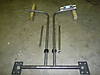
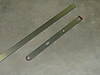
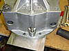
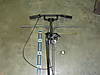
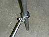
Today I managed to get a good deal of machine work done. I started by working on the mount for the handlebars/laterals. I spent some time getting the handlebars positioned at the right height and angle in the Argo. Then I took them out and notched them so that they fit on the tubing at the right angle for welding (I went with a 10 degree kick in on the handlebars). You can see the whole assembly that I am going to be using in this photo. The only thing I didn't get to finish was machining out a hole in the end plates for the tubing to slide through. The two outer tubes will be welded to the outer plates. Those plates will bolt to the Argo frame with a solid rod in between them that the laterals will rotate on.
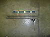
I also got some machine work done on the extended popsicle stick levers for the T20. Originally I had one cut out on a laser from regular steel for mockup. Since those dimensions worked, I'm now just recreating it on the milling machine out of A2 tool steel. Once they are complete I will have them hardened. I just used a grinder to put the radius on the ends and then milled out the holes/slots.
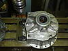
Today I managed to assemble part of the T20. I have a bent output shaft on the other side of the T20 so I have to order a new one before I can finish assembling the transmission. By assembling the left (input shaft) side of the T20, that allowed me to slide the clutch on and mock up the placement of the engine with the belt. Then I marked the location of the engine mounting bolts and machined out slots in the engine mount to allow for side-to-side adjustment of the T20 for proper belt alignment.
I also ordered a throttle to try out on the Avenger. It is called the dual gasser throttle. It has a twist throttle and a thumb throttle. The twist throttle is lockable so that it does not rotate when you want to use the thumb throttle. I had been searching for a unique throttle for a while when I stumbled upon this one. There weren't many specifications on this throttle online but I took a gamble and ordered it anyway. I haven't torn it apart yet to see if I can make it work with a throttle cable for the Briggs motor but I'm sure it will be fine.
looks similar to what I made for my copperhead a couple of weeks ago less the case mod.
Marc, it was funny. I was picking on your black oxide rod ends in a comment under your photo several days ago. Well, I went to order mine and the black oxide ones were the only ones I could find from the couple of places I was already ordering parts from.
Some more parts arrived this week so I was able to make some progress today. I started by pressing a 3/8" x 2" dowel pin into the T20 case halves. I used an arbor press to press them in. I also used some green Locktite retaining compound just for added insurance that they would stay put.
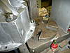
I had ordered some eyebolts to use in the T20 plungers and they arrived. The only ones I could find were too long so I cut them down and used a die to clean the threads. I installed them and they were a little too thick. They caused the popsicle stick lever to be at an angle instead of being parallel with the case. So I machine the face of the eyebolts down about 1/32" each and that put the levers parallel with the case.
Once I had the lever where I needed it, I machined out some spacers to fill the void between the boss on the T20 case and the levers themselves. The old style T20 cases had longer bosses that extended all the way to the levers. The newer C-channel cases have shorter bosses to accommodate the extra width of the C-channel levers. For mockup, I used some bolts through the eyebolts but I will be using clevis pins in the end to hold the levers in place.
The main bracing for the motor mount is now finish welded. I have to wait to get the T20 back together before I can build the top plate as I will have to align the clutches to locate the motor.
I didn't get but an hour or so tonight to work on the Argo but I did manage to get a couple of small things done.
I started by bending the 7/8" DOM tubing for the laterals. I am going to try out some horizontal bars this time to see how I like them. I am probably going to try out a thumb throttle too. For now I made both ends of the handlebars longer than needed. I will cut them down when I get further along.
I will also probably weld them at a slight angle to match the stock Avenger bars as they are pretty comfortable.
I scratched my head for a while on different solutions for mounting the T20 linkage to the laterals. Since the T20 moves up to tighten the output shaft chains, I needed a way to move the linkage mounting point up with it as well. Tonight I welded a tab on a wide two-piece collar and I think that is going to work well.
Updating this thread is helping to keep me moving forward. I feel like I made some decent progress today.
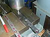
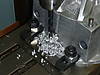
I machined the hole in the T20 case halves for a press fit to allow me to press in 3/8" dowel pin / pivot point for the new popsicle stick style levers. I started with a 1/8" bit and drilled completely through the case with it.
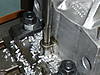
Then I went to an undersized drill bit and finished the hole out with a slightly undersized reamer as well. With the large hole, I only drilled to the bottom of the boss. I have to order some longer dowel pins, otherwise I would have gone ahead and pressed them in.
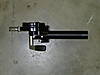
After I got the holes machined in the T20 case, that allowed me to mock up the new lever that I made. I cut out this lever just for mock up. The bottom of the lever was extended about 2" compared to the stock ones to allow me to position the linkage that will go to the laterals right below the T20 mount. In these photos, I am using heim joints instead of eye bolts in the T20 plungers so they throw the lever at a slight angle. Also, the dowel pin is just sitting in the hole. Both of those will be changed but this was mainly to make sure the lever was extended to the right position. Now that I know it is, I will machine out two more levers and have them hardened.
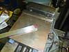
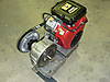
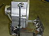
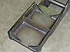
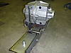
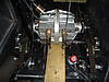
Finally, I started making the motor mount that will sit on top of the existing transmission mount that I've already finished. In these photos I have most of it tacked together. As you can see, the bottom mount is slotted to allow this top motor mount to slide forwards and backwards for proper belt tension. Once I weld this up, a final plate will be welded to the top. That plate will be offset towards the clutch side of the motor for proper belt alignment. The top plate will also have slots machined in it to allow the motor to be slid from left to right for fine tuning of the belt alignment. Depending on how far the plate has to be offset I may end up having to add a "leg" under it to support the weight of the motor. I won't know for sure until I get the T20 back together and in the mount so I can line up the clutches and mark the holes needed for the motor mount.
This photo shows the motor mount slid all the way forward.
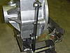
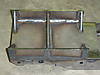
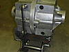
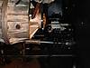
This photo shows the motor mount slid all the way to the rear.
Looks great, Mike! That DOM tubing is expensive stuff, and the more you need, it seems to REALLY add up quickly. I can't believe how fast this project is coming along.
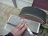
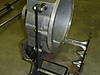
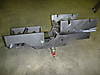
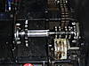
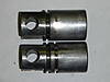
Tonight, I installed the intermediate shafts back in the Argo. The splines have been extended to allow me to slide the sprockets further towards the outside of the Argo. This was needed to line up with the T20 output shaft sprockets since the T20 is wider than the stock Avenger transmission.
Sprocket slid all the way towards the transmission
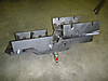
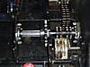
Sprocket slid all the way towards the outside of the Avenger
Here are a couple of older photo where you can almost make out the length of the original splines for comparison
I also placed orders for lots of small parts I needed and picked up some DOM tubing to make the laterals and the linkage.
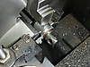
I spent most of the couple of hours that I had free today machining parts. I made some spacers to allow me to press the new T20 sprockets onto the T20 output shafts to exactly the right place. I also placed the shafts in the freezer tonight so they will be ready to press on. I cut new grooves in the four T20 plungers while I had them out to upgrade them from the single oring to the double oring style.
I also managed to get one half of the T20 case secured to the milling machine's table. It is ready for me to drill out the boss for the dowel pin pivot. I was busy for several hours but it doesn't feel like I got much done today.
Please make sure to document all of the dimensions of your Argo ' T-20 engine mount ' from front, side to side, height, and length for other forum members that have thought about doing this very same T-20 conversion. Great work so far.


Leave a comment: