
 Tweet
Tweet
Looks great Mike!
-
Life should not be a journey to the grave with the intention of arriving safely in an attractive and well-preserved body, but rather to skid in sideways , cigar in one hand, whiskey in the other, body thoroughly used up, totally worn out and screaming "WOO-HOO, what a ride!!!" -
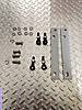
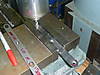
Some more parts arrived this week so I was able to make some progress today. I started by pressing a 3/8" x 2" dowel pin into the T20 case halves. I used an arbor press to press them in. I also used some green Locktite retaining compound just for added insurance that they would stay put.
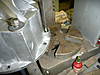
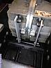
I had ordered some eyebolts to use in the T20 plungers and they arrived. The only ones I could find were too long so I cut them down and used a die to clean the threads. I installed them and they were a little too thick. They caused the popsicle stick lever to be at an angle instead of being parallel with the case. So I machine the face of the eyebolts down about 1/32" each and that put the levers parallel with the case.
Once I had the lever where I needed it, I machined out some spacers to fill the void between the boss on the T20 case and the levers themselves. The old style T20 cases had longer bosses that extended all the way to the levers. The newer C-channel cases have shorter bosses to accommodate the extra width of the C-channel levers. For mockup, I used some bolts through the eyebolts but I will be using clevis pins in the end to hold the levers in place.
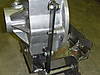
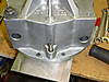
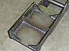
The main bracing for the motor mount is now finish welded. I have to wait to get the T20 back together before I can build the top plate as I will have to align the clutches to locate the motor.
Comment
-
looks similar to what I made for my copperhead a couple of weeks ago less the case mod.
 Acta non verba
Comment
-
Marc, it was funny. I was picking on your black oxide rod ends in a comment under your photo several days ago. Well, I went to order mine and the black oxide ones were the only ones I could find from the couple of places I was already ordering parts from.Originally posted by jerseybigfoot View PostComment
-
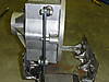
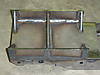
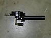
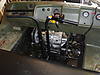
Today I managed to assemble part of the T20. I have a bent output shaft on the other side of the T20 so I have to order a new one before I can finish assembling the transmission. By assembling the left (input shaft) side of the T20, that allowed me to slide the clutch on and mock up the placement of the engine with the belt. Then I marked the location of the engine mounting bolts and machined out slots in the engine mount to allow for side-to-side adjustment of the T20 for proper belt alignment.
I also ordered a throttle to try out on the Avenger. It is called the dual gasser throttle. It has a twist throttle and a thumb throttle. The twist throttle is lockable so that it does not rotate when you want to use the thumb throttle. I had been searching for a unique throttle for a while when I stumbled upon this one. There weren't many specifications on this throttle online but I took a gamble and ordered it anyway. I haven't torn it apart yet to see if I can make it work with a throttle cable for the Briggs motor but I'm sure it will be fine.
Comment
-
Coming together nicely Mike , hope to see it in action soon. Got any left overs? Going to do a build soon, pm me if you want. Jimsigpic
My new beer holder spilled some on the trails - in it's hair and down it's throat.
Joe Camel never does that.
Advice is free, it's the application that costs.Comment
-
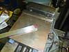
Today I managed to get a good deal of machine work done. I started by working on the mount for the handlebars/laterals. I spent some time getting the handlebars positioned at the right height and angle in the Argo. Then I took them out and notched them so that they fit on the tubing at the right angle for welding (I went with a 10 degree kick in on the handlebars). You can see the whole assembly that I am going to be using in this photo. The only thing I didn't get to finish was machining out a hole in the end plates for the tubing to slide through. The two outer tubes will be welded to the outer plates. Those plates will bolt to the Argo frame with a solid rod in between them that the laterals will rotate on.
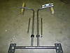
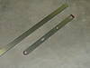
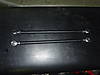
I also got some machine work done on the extended popsicle stick levers for the T20. Originally I had one cut out on a laser from regular steel for mockup. Since those dimensions worked, I'm now just recreating it on the milling machine out of A2 tool steel. Once they are complete I will have them hardened. I just used a grinder to put the radius on the ends and then milled out the holes/slots.
Comment
-
 Very nice work Mike!
Life should not be a journey to the grave with the intention of arriving safely in an attractive and well-preserved body, but rather to skid in sideways , cigar in one hand, whiskey in the other, body thoroughly used up, totally worn out and screaming "WOO-HOO, what a ride!!!"
Very nice work Mike!
Life should not be a journey to the grave with the intention of arriving safely in an attractive and well-preserved body, but rather to skid in sideways , cigar in one hand, whiskey in the other, body thoroughly used up, totally worn out and screaming "WOO-HOO, what a ride!!!"Comment
-
Looking good Mike!!!!!!!!HUSTLEMANIAC and a HONORARY MEMBER of the
BIGFOOT ALUMNI
Comment
-
Congrats Mike, Looks like a nice machine. Have fun with it."I'm NOT stuck, I'm just temporarily stopped"Comment
-
Just a simple suggestion Mike.. I would add grease fittings to the bottom of the laterals so that you can keep grease on the rod that supports the laterals. Kinda like I did on my hustler..
Comment
-
good idea Dan67. i had to heat my laterals in a vice with a torch to get them apart and free them up and grease the heck out of them. I did not put grease fittings but drilled holes for lube.grease fittings are the best way to go.moving parts like laterals need to be free moving or premature band wear can happen.Originally posted by Dan67 View PostComment
-
 Very Nice Mike !! Looks great!!
Comment
-
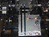
With spring weather, progress on this project has slowed some but I have managed to get a few things done.
I got the laterals painted and mounted. I still need to pick up a few more bolts but the couple that I have will hold everything in place for now.
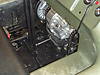
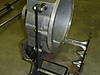
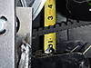
I got the T20 completely together and was able to mount it today to finalize the length of the control rods. Once the length was correct, they were welded and painted and are ready to go.
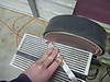
I was able to drape some #60 chain from the T20 to the sprockets to make sure the chain clears on both sides and it does. I have to buy some more #60 so I counted pins and wrote down how much I need to order.
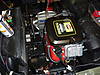
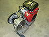
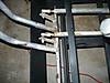
I also checked the belt clearance after raising the motor mount and it looks like it should work fine. I will definitely be watching it once I finally start the motor up just to be sure the oscillation of the belt doesn't cause it to hit.
I just have the top plate of the motor mount tacked into place right now. I need to make a modification to it to move it 3/4" but beyond that, I decided to extend the mount about another 6" to the left from what you see in this photo to give me a place to mount the air intake/duct that I will have to build to direct air to the motor.
Comment
-
Mike, ur awsome with this modification. Can't wait to hear the final outcome with the steering performance.Comment

Comment